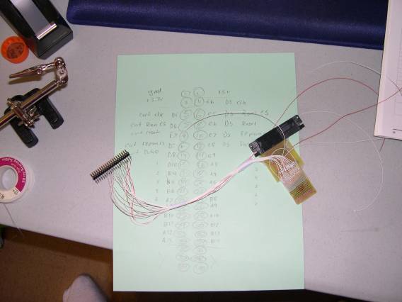
DS Development - passthru

I've ripped up my old DS sniffer, and am reworking it into a proper passthru.

Pictures


My original DS sniffer


Removed the old wires, and cut the traces


Added the DS wires


Added the cart connection wires


Ahh, it's ready to go.. now to write some firmware...


Passthru firmware written, metroid runs perfectly :)


Additional firmware written to enable homebrew development - it works very well :) (joat's 2-screen demo)


DesktopMan's TetrisDS


I've decided to release the code I'm using on my fpga board for other people who want to build a passthru. The vhdl code was written with Xilinx ISE WebPack, and is running on a Digilent Spartan-3 FPGA Starter Board. The zipped project folder can be download Here.
Don't ask me where to find Xilinx ISE or the board I'm using, they're easy to find on the web.
Here's a list of the specific pins I'm using, however the ucf can be modified to use whatever set of pins you want. - I'm using the A2 port
(If you don't know what to do with this information, you're probably better off learning more before you continue)
FPGA PinFPGA Board Connector LocationDS/Cart connection
E6A2 #4DS - pin 2 - CLK
C5A2 #6DS - pin 4 - ROM CS
C6A2 #8DS - pin 5 - RST
C7A2 #10DS - pin 6 - EEPROM CS
C8A2 #12DS - pin 9 - Data bit 0
C9A2 #14DS - pin 10 - Data bit 1
A3A2 #16DS - pin 11 - Data bit 2
A4A2 #18DS - pin 12 - Data bit 3
A5A2 #20DS - pin 13 - Data bit 4
B7A2 #22DS - pin 14 - Data bit 5
B8A2 #24DS - pin 15 - Data bit 6 / serial from EEPROM
A9A2 #26DS - pin 16 - Data bit 7 / serial to EEPROM
D5A2 #5Cart - pin 2 - CLK
D6A2 #7Cart - pin 4 - ROM CS
E7A2 #9Cart - pin 5 - RST
D7A2 #11Cart - pin 6 - EEPROM CS
D8A2 #13Cart - pin 9 - Data bit 0
D10A2 #15Cart - pin 10 - Data bit 1
B4A2 #17Cart - pin 11 - Data bit 2
B5A2 #19Cart - pin 12 - Data bit 3
B6A2 #21Cart - pin 13 - Data bit 4
A7A2 #23Cart - pin 14 - Data bit 5
A8A2 #25Cart - pin 15 - Data bit 6 / serial from EEPROM
B10A2 #27Cart - pin 16 - Data bit 7 / serial to EEPROM
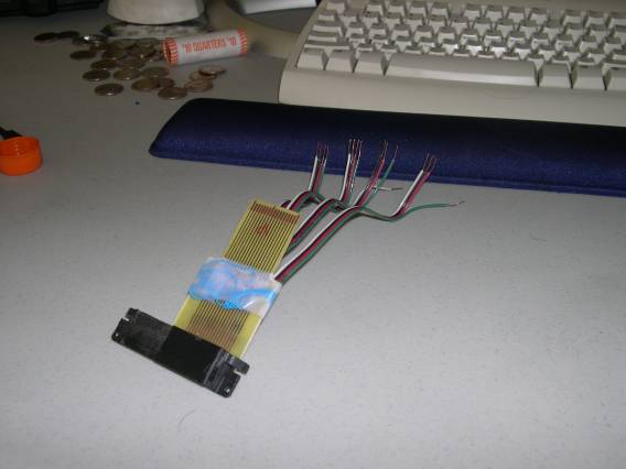
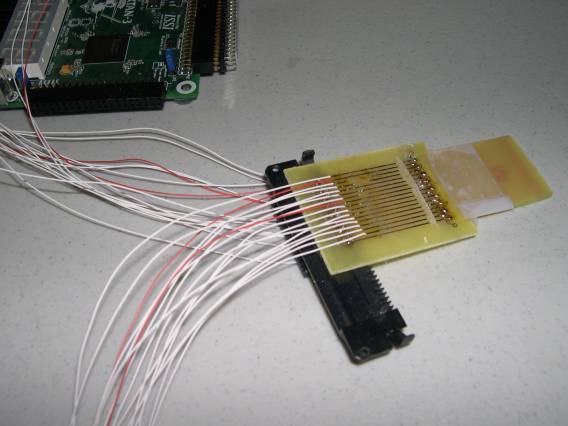
Additionally, the DS and Cart pins 1 and 17 are tied to ground, DS and Cart pins 3 are unconnected, DS pin 7 is connected to ground, Cart pin 7 is unconnected, and DS and Cart pins 8 are connected together.

Besides those pins, the first two switches (next to the PS-2 port) and the leds are defined in the project. The leds are set to nothing at the moment, just turned off, and the switches behavior is defined as follows: (SW0 and SW1 are markers printed on the pcb)
SW0SW1Behavior
OFFOFFPure Passthru (plays game attached to passthru)
OFFONPure Passthru (plays game attached to passthru)
ONOFF"Hack" Passthru (Boots game, but ARM7 address is reset to the GBA cart)
ONON"Hack 'n Skip" Passthru (Bypasses the menu, no key press is necessary for intro screen, ARM7 address is reset to the GBA cart)